

|
ElectronicsOverview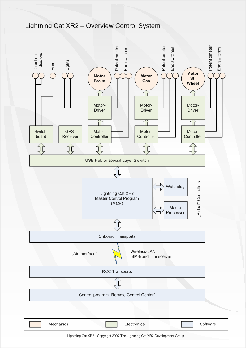 The electronically control of Lightning Cat XR2 was specially developed and made for this project and no components were bought. The following diagram clarifies the construction of the system: Power supplyBeside the 12V car-battery, Lightning Cat XR2 also uses two additional 12V, 36Ah car-batteries which are switched in a row. These two extra added batteries assure the electric power supply of the whole control system. During the realization of the electric power supply, we have also paid attention, that the power supply of the car was strictly separated from the power supply of the control system to avoid all kinds of negative influence between these two circuits. Bus systemThere exist two conrecte implementations for the bit transmission layer between the controllers:
In Lightning Cat XR2 we use the first alternative, because of the reasons of economy. The second alternative exists only as a simulation model. But concerning interference resistance and fail-safe, alternative 2 has some obvious advantages. Other bus system and protocols (CAN, Ethernet) are unqualified, because of their, in this case, needless complex demands to the controller. Switchboard The switchboard is a simpe relay-board with 8 potential-free outputs with each maximum 10A. We use this component to control the turn signals, the front- and backlights and the signal-horn. Motorcontroller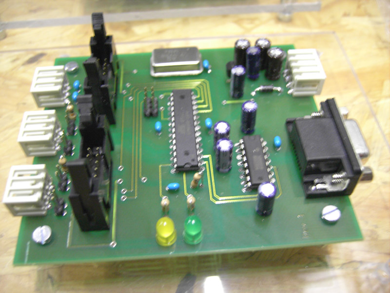 This controller exists in 3 different versions, whereas the hardware is always the same and only the software deflects lightly. To gather the position of each motor, we use a precision-potentiometer, which is connected to an internal ADC of the ATMega8 controller. The resolution of the ADC is 10 bit. Via the control program, different configuration values can be calibrated: allowed range of action of the controlled motor, position tolerance and a so-called "softrange". If the target positions diverges from the actual position less than the “softrange” value, the motor is driven in a controlled PWM-mode to acquire the position more exactly. Beyond this range, the motor is driven with full power. To enhance the output, a motor controller can control up to two motordriver units. Different safeguards (three-stage watchdog system, end switches and current monitoring) make sure that safe operations of the different key systems are given. Motordriver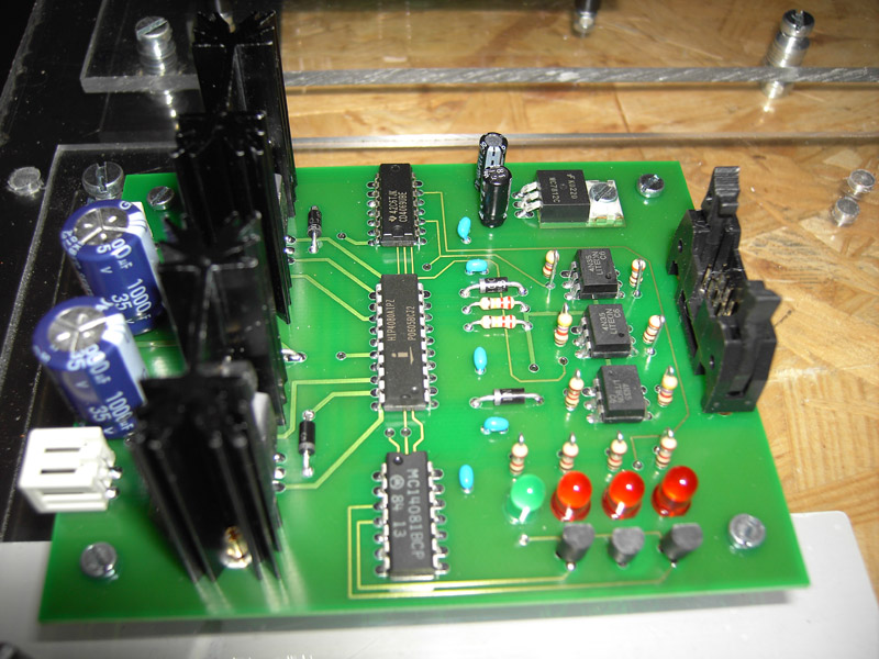 The driver comprises the power transistors for the separate motors. Power element and control input are naturally, galvanically separated by optocouplers. The motors can be controlled with maximum 10A steady current at 24V. A
momentary load up to 15A is also possible. Data transmissionIn a close-up range, Lightning Cat XR2 uses Wireless LAN (IEEE 802.11g) to transmit the control commands and telemetry. The cruising range is limited to 250-300 meters. To outrange the transmission up to 4km, it is possible to use ISM-band transceivers. If normal conditions are given, the data transfer rate of each direction (Uplink/Downlink) of the control connection is not beyond the 6 Kbit/s barrier (750 B/s). A simply change between the different transmission modes, during the going handling, is possible without breaks. This is possible with the usage of so-called transport-drivers. |